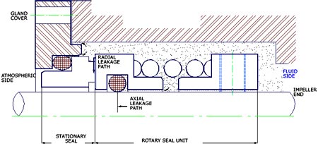
Seal Fundamentals
By rated pressure
a) Unbalanced Seal – 95%: Below 12 ATM-Absolute
b) Balanced Seal – 5%: Above 10 ATM-Absolute
By Number of Units per installation
a) Single Seal- 90%
i) Spring(s) fitted on Rotary unit
ii) Spring(s) fitted on Stationary unit
b) Double Seal -<10% (Estimate only)
c) Multiple Seal -<1% (Estimate only)
By Mounting Arrangement
a) Inside seal – 95%: Rotary unit with spring inside
b) Outside seal- 5%: Rotary unit with spring outside
By Method of Mounting
a) Cartridge seals: Completely pre-assembled and preset at factory;
b) Conventional seals: individual seal parts handled separately, and seal assembled on pump by taking measurements as per seal instruction sheet/drg..
By Design Complexity
a) Simple systems with single helical spring;
b) Complex systems with multiple springs;
c) Mass produced systems with pressed metal components

Note 3 : Always refer to technical drawings/fitting instructions enclosed in the seal box before starting fitment. If no drawings are to be found inside, you can obtain a copy from General Seal, or refer to that section of the equipment instruction manual dealing with seal design and handling. | |
Note 4 : The fluid film between the sealing faces may be destroyed by vibration in running gear, by cavitation in impeller, by dry running of seals inside the seal chamber,and by other causes that force the seals to operate outside their design limits. This will result in higher frictional contact between the sealing faces, and reduce seal life. | |
Note 5 : The frictional heat inside the seal-chamber or stuffing box MUST be removed by use of flushing media; all flushing lines/fluid circulation lines to & from seal chamber must be kept in good order and kept connected to the seal chamber during operation | |
| Seal Faces |
The Stationary and the Rotary seal faces are rubbing against each other at high surface speeds inside the seal chamber or stuffing box. This rubbing process generates intense heat and wear due to frictional properties of the seal face material. To control the heat and wear, it is necessary to choose material having very low coefficient of friction, while at the same time, they should be very hard to resist wear. Based on decades of experience, it has become possible to standardise seal face material combinations by using a softface made of resin-impregnated carbon ring to run against a hard metaloxide ring. Carbons come in many grades; based on the level of durability, they are priced from the cheap/mass-produced grades to expensive, metal-powder impregnated varieties. Metal oxides, called Ceramics, also come in many grades of purities, and chemical composition, that determine the final price of the product. The choice of carbon and ceramics is based on considerations of their low coefficients of friction. Also ceramics are very very hard, next only to diamonds in hardness, which results in superior wear-resistance properties. Metals exhibit significantly higher frictional coefficients, but are less brittle than ceramics. Also Metals in seal faces have exceptional thermal cycling properties compared to ceramics. |
| Common Seal Face Materials |
|
| Material of Construction |
| Elastomers |
Elastomer means elastic-like material. In seals, Rubber O-rings are the sealing elements, but at times it is necessary to use other material for such sealing: e.g., PTFE Wedges, PTFE U-Cups, Rubber Bellows, etc. All such elements are grouped under the general term of ‘Elastomer’. Because of their excellant flexibility, rubber o-rings are the near-universal choice for elastomer in seals. Only in cases where the rubber is incompatible with the fluid media does the choice fall on non-rubber elastomers such as PTFE. “Rubber” is a very loose term; it encompasses a wide variety of elastic material that exhibit varying degrees of temperature / chemical / environmental tolerance. Inside the seal, the O-ring is subject to static deformation due to the “squeeze” imposed on it as well as the heat generated within the seal housing due to the frictional forces (and other heat sources). The effect of this is to reduce the flexibility of the O-ring over a period of time, and eventually the O-ring loses all its elastic properties. Such an O-ring, without elasticity, is said to be a “COMPRESSION-SET”O-ring. |
| A seal with a compression-set O-ring will leak. |
As in other cases, the choice of a particular grade of material for O-ring influences the seal performance and its price. Material such as Nitrile and Neoprene are relatively low-cost, and are satisfactory for temperatures below 60%d C. At the high end of price and performance are proprietory grades such as VITON. Other proprietory grades of rubber elastomers include Du Pont’s Kalrez and 3M Corp.’s Aflas. These grades represent some of the most expensive materials among elastomer grades. Most expensive doesn’t necessarily mean compatible with ALL chemicals and high temperature tolerance; even these elastomers cannot be used in certain common applications where lower priced elastomers give better performance. PTFE’s (Poly Tetra Fluoro Ethylene) are not elastic in nature, but in seal application they are classified as elastomers. They are used in applications where rubber o-rings are ineffective – e.g., in chemically corrosive or in high temperature (upto 250 degree C.) applications. For very high temperature applications (say, over 200 degree C.), general practice is to eliminate usage of any type of elastomers in seals; in such cases, all-metal seals are used in the form of metallic bellows. |
| Other Body Material |
The commonest material for seal body parts is Stainless Steels (Grades 304 or 316). Cheaper than these are sundry metals like brasses/bronzes/cast-irons/steels/etc. Springs, Grub Screws, Drive Pins, Drive Screws, etc., are all in St.Steels. For very corrosive applications use seal body parts is made of superior grades of metal alloys For many corrossive applications, PTFE is used as Body material in contact with the fluid medium. |


 HYDRAULIC FORCES ACTING ON SEAL FACES OF UNBALANCED SEALS.


GLOSSARY | |
| H.S.D. : | Hydraulic Sealing Diameter |
| Hydraulic Closing Area | |
| Hydraulic Closing Pressure | |
| Seal Face Area | |
| Seal Face Pressure | |
| Forces Cancelled | |
| Forces Acting | |
| (R) : | Rotary Seal Ring |
| (S) : | Stationary Seal Ring |